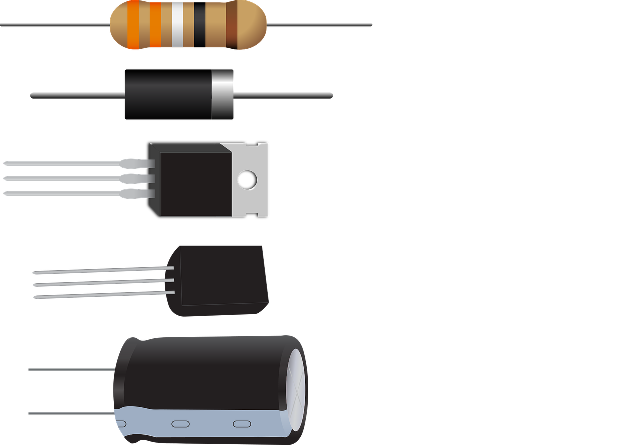
Smt pick and place machine SMD How To Select A Capacitor Circuit Diagram Polarized capacitor; Non-polarized capacitor; The difference between a polarized capacitor and a non-polarized capacitor is that the polarized capacitor has a positive and a negative side. So it must be placed with the positive pin where the most positive voltage is. You can place the non-polarized capacitor in any way you want. In such cases, a series or parallel combination of capacitors can be used to get the desired capacitance in the circuit. When capacitors are connected in series, the equivalent capacitance is given by the following equation: 1/C series = 1/C 1 + 1/C 2 + 1/C 3 + . . . . When capacitors are connected in parallel, the equivalent capacitance is
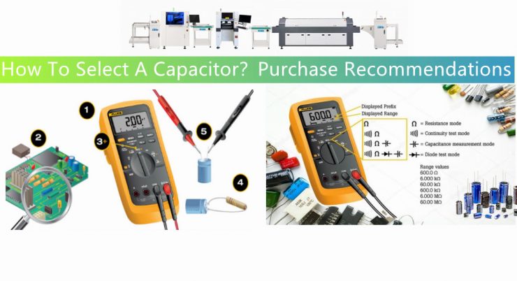
Selection: Match the value specified in your circuit design. Use standard values (e.g., 10μF, 100nF) unless precision is critical. B. Voltage Rating. Definition: The maximum voltage a capacitor can withstand without breakdown. Rule of Thumb: Choose a rating ≥1.5× the circuit's operating voltage. For example, use a 25V capacitor for a 12V 6 Regulator Slew Rate Example Circuit.. 9 7 High Frequency Impedance Plot 2 Input and Output Capacitor Selection SLTA055-FEBRUARY 2006 Submit Documentation Feedback. www.ti.com 1.3 Calculating Ceramic Capacitance C MIN I OUT dc (1 dc) 1000 f SW V P(max) dc V OUT V IN; Efficiency (1) C MIN Ceramic Capacitors: Application: Widely used for general-purpose coupling, decoupling, and filtering applications. Values: Available in a wide range of capacitance values, typically from picofarads (pF) to microfarads (µF). Example: Ceramic capacitors are commonly used in power supply circuits for smoothing and decoupling. Electrolytic Capacitors:
How to Choose the Right Capacitor Types Circuit Diagram
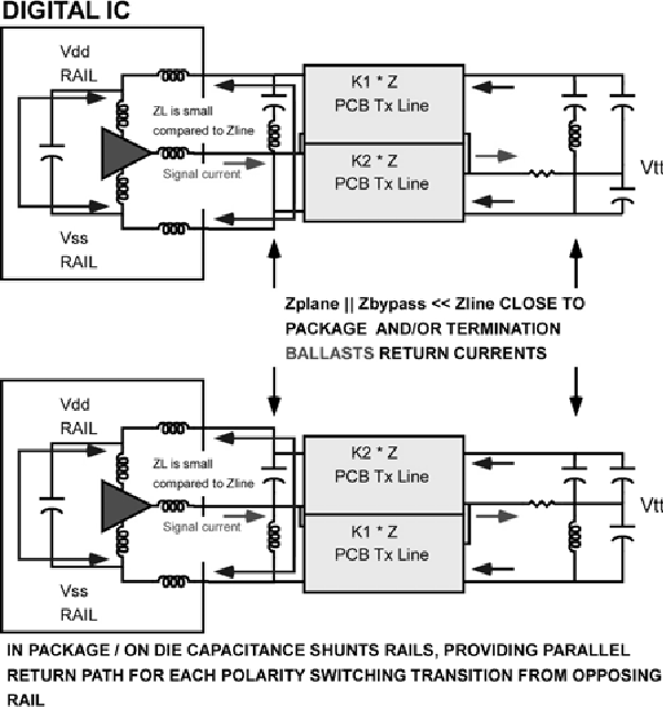
This guide explains the role of capacitors on circuit boards, covering their types, functions, selection criteria, and troubleshooting techniques. It provides practical insights for engineers, designers, and hobbyists to optimize circuit performance and repair faulty components. Connecting a 1 µF capacitor from VIN to GND reduces the circuit sensitivity to the printed circuit board (PCB) layout, especially when long input traces or high source impedance are encountered. If greater than 1 µF of output capacitance is required, the input capacitor should be increased to match it. Input and Output Capacitor Properties 7. How to Select Capacitors Considering Life Expectancy. Capacitor life or lifetime expectancy is the length of time the capacitor will stay healthy as designed. This is critical for electrolytic capacitors. For ceramic capacitors, this is not an issue and probably not worth to look in to when selecting capacitors for small signal circuits.