PWM Based DC Motor Speed Control using ARDUINO Microcontroller 2019 Circuit Diagram Small DC motors ideal for use in applications where speed control is required such as in small toys, models, robots and other such electronics circuits. A DC motor consist basically of two parts, the stationary body of the motor called the "Stator" and the inner part which rotates producing the movement called the "Rotor".
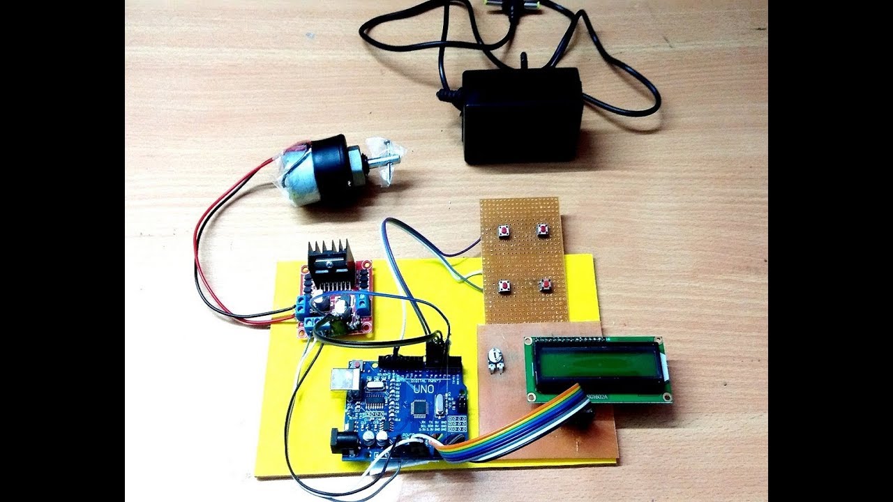
Here we will use a technique called PWM (Pulse Width Modulation) to control the speed of DC motor. We can achieve speed control of DC motor using mechanical or electrical techniques but they require large size hardware to implement but a Microcontroller based system provides an easy way to control the speed of DC motor. Earlier, we have already
How to Use Pulse Width Modulation (PWM) in Motor Control Circuit Diagram
A complete block diagram utilizing a H-bridge IC LMD15200, 3 A, 55 V and a pulse width modulation IC LM3524D to drive the H-bridge motor controller input is shown below: Motor speed control using a H-bridge. The speed set point is controlled with a potentiometer or input voltage value. A tachometer is attached to the motor (M) to sense the

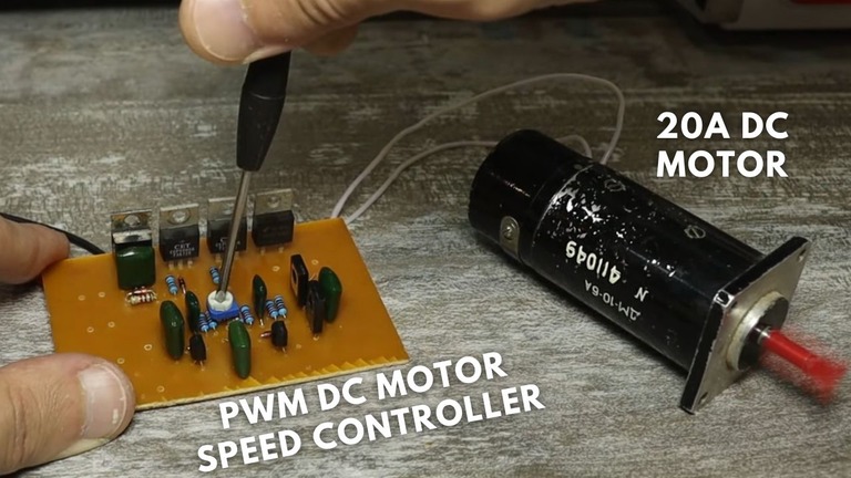
By adjusting the length of the ON/OFF pulses, we can set the voltage to anywhere between 0V and the maximum voltage. We will use this PWM signal to power the motor directly. PWM Motor Driver. There are several ways to generate the PWM signal for the motor, but in this tutorial we will use the 555 timer. Here's a schematic of the circuit:
Speed Control of DC Motor Using Pulse Width Modulation Circuit Diagram
Controlling the speed of a DC motor while simultaneously monitoring its current consumption is an essential aspect of many robotics projects, motorized systems, and energy-efficient applications.In this tutorial, we'll walk you through how to control a DC motor using PWM (Pulse Width Modulation) and measure the current drawn by the motor using the ACS712 current sensor with an IRF540N MOSFET In this project, I will show How Speed Control of DC Motor can be implemented using 555 and Pulse Width Modulation (PWM). We use DC Motors in many systems in our day to day life. For example, CPU fans, fume extinguishers, toy cars etc. are all DC Motors which are operated by DC power supply.
